The LC&M allows for both conventional DC throttle control and digital DCC command control. Each block is switched between the two, allowing connection to either the conventional or digital buss. All blocks are gapped in both rails, and all block switches have a center-off position, allowing any block to be isolated.
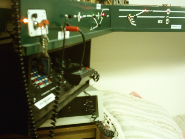
Shown here is the MAIN CONTROL POSITION at McKerrow, Ontario (on the shelf top, you are looking at the east leg of the McKerrow wye in the foreground; in the background, you can see the west leg of the wye, and across the back of the shelf, the main track - the CPR Webbwood Subdivision - and the west siding switch McKerrow; the two CP Rail Budd RDCs are sitting at the west end of the siding):
The dark green fascia runs around the layout. On it can be seen the following, running from left to right:
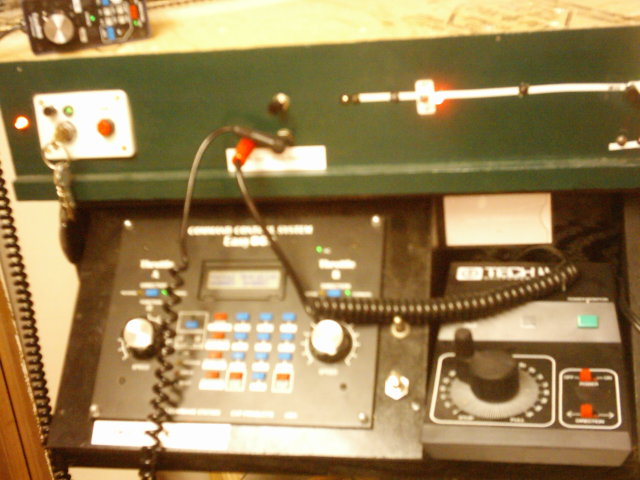
Below the fascia in this corner is the roll-out throttle shelf. On it can be seen the EasyDCC command station and a conventional DC MRC Tech II PWM throttle. The photo below shows the throttle shelf more clearly. It also shows two controls not mentioned above, between the two throttles:
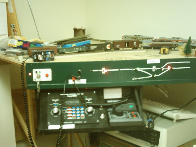
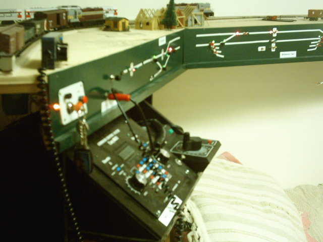
The photo below gives a view of the whole corner, and shows the profile of the roll-out shelf, as well as a view past the corner, where the track schematic for McKerrow Yard can be clearly seen.
When not in use, the roll-out tray can be pushed in flush with the fascia, to allow more clearance when using the room for other purposes - a primary condition of continued marital bliss, if you get my drift; the photo below shows the tray pushed in and also allows a view of the vintage IBM PC 5150 which runs the sound system mentioned above. The two sound controls (bell and horn/whistle) connect to inputs on the serial port, and a DOS-based interrupt-drive program which runs on the PC is used to interpret the button presses, and plays looped actual recorded audio samples of locomotive bells, steam whistles and diesel horns. Output is produced with a Sound Blaster card and is fed to the room's stereo amplifier through a mixing console.